Large‑scale battery energy storage deployments traditionally involve extensive on‑site assembly work, bringing scheduling risks, wiring faults and extended commissioning timelines for project teams. Utility‑Scale Containerized Battery Energy Storage System delivers pre‑tested, factory‑integrated megawatt‑class storage units ready for on‑site placement and connection. This article explores its dual‑capacity variants, built‑in safety architecture, manufacturing workflows, real‑world project feedback and key considerations for developers and EPC teams evaluating container‑format energy‑storage assets.
On This Page — Click links to jump to section
1. What Arrives On The Truck For Container‑Based Storage Projects
Conventional megawatt‑hour storage projects perform most assembly activities on‑site. Battery packs come delivered on pallets, rack structures get erected locally, large volumes of field cabling are routed and connected, and much of the commissioning schedule gets consumed resolving wiring errors introduced during field installation. Utility‑Scale Containerized Battery Energy Storage System reverses this typical project sequence.
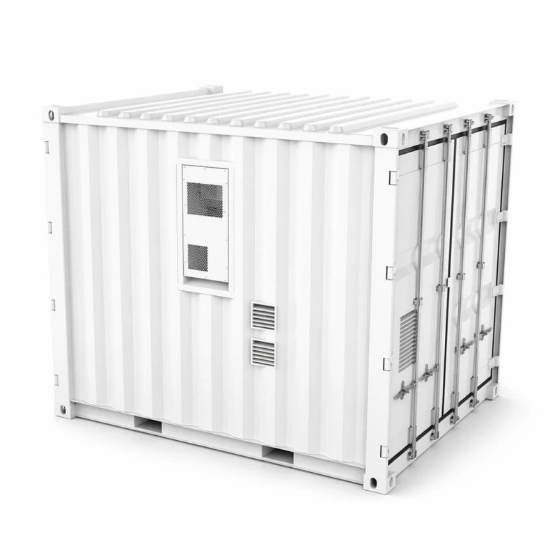
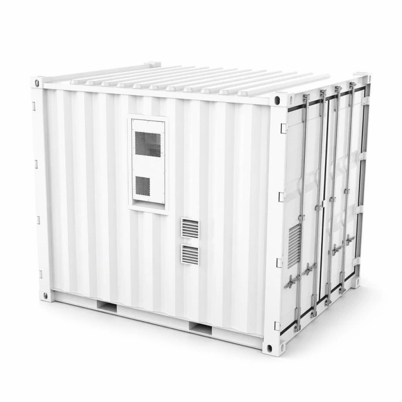
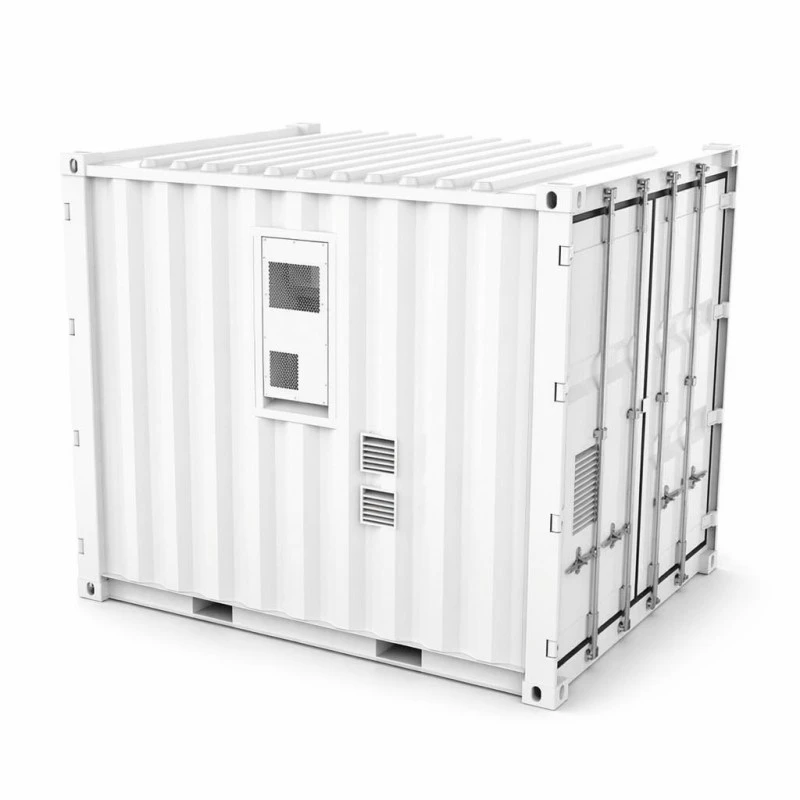
The complete set of battery packs, air‑cooled thermal circulation hardware, dual fire‑suppression assemblies and full monitoring cabling are fully integrated within factory facilities located in Yueqing. Every subsystem undergoes combined system‑level testing before shipment inside the 3048*2438*2591‑millimetre enclosure. Once delivered to project premises, site crews position the container onto prepared concrete pads, run DC bottom‑entry cabling towards the site PCS and EMS hardware, then proceed to commissioning activities. By shifting assembly and system validation into factory workflows, these critical tasks no longer occupy the project’s critical‑path timeline, representing the core value proposition for selecting a container‑style solution over discrete rack‑based storage systems.
2. Two Capacity Variant Overview And Core Technical Parameters
The same physical container footprint supports two distinct energy‑capacity configurations, 1060kWh and 1215kWh. Project civil engineering, concrete pad specifications and crane lifting plans stay unchanged regardless of which variant gets selected, simplifying pre‑construction site preparation work. String architecture differs for each configuration: 48 battery packs implement 4P264S topology for 1060kWh (nominal 844.8VDC), and 55 packs implement 5P242S topology delivering 1215kWh (nominal 774.4VDC). Both variants keep output within the widely‑accepted 680‑950VDC operating window compatible with most mainstream large‑scale PCS hardware platforms.
Standard charge and discharge current sits at 200A for both versions operating at a 0.5C rate, aligning DC‑side output with typical project bus architecture requirements. Maximum system‑level efficiency reaches 88 percent measured across one full charge‑discharge cycle including auxiliary power consumption rather than battery‑only metrics. Cycle‑life performance exceeds 8000 cycles under 0.5C and 25‑degree‑Celsius ambient conditions while retaining a minimum of 80 percent energy capacity, and operational ambient temperature ranges sit between 0°C and +50°C matching the container’s internal air‑conditioning thermal management.
| Category | Parameter | 1060kWh Model | 1215kWh Model |
|---|---|---|---|
| DC Side | Rated capacity | 1060kWh | 1215kWh |
| Cell type | LFP 3.2V/314Ah | LFP 3.2V/314Ah | |
| Battery system string | 4P264S | 5P242S | |
| PACK specification | 70.4V314Ah | 70.4V314Ah | |
| NO. of PACKs | 48 PCS | 55 PCS | |
| Nominal voltage | 844.8VDC | 774.4VDC | |
| Voltage range | 680~950VDC | 680~950VDC | |
| Standard charge/discharge current | 200A | 200A | |
| System parameters | System efficiency | MAX.efficiency 88% @0.5C / 1 Charge 1 Discharge | MAX.efficiency 88% @0.5C / 1 Charge 1 Discharge |
| System lifespan | >8000Times(0.5C@25°C) Energy retention rate ≥ 80% | >8000Times(0.5C@25°C) Energy retention rate ≥ 80% | |
| Wiring method | DC bottom entry | DC bottom entry | |
| Charge & discharge rate | 0.5CP | 0.5CP | |
| Thermal management method | Intelligent air‑cooled air conditioner | Intelligent air‑cooled air conditioner | |
| Communication protocol | CAN/Eth/RS485(4G Optional) | CAN/Eth/RS485(4G Optional) | |
| Fire protection system | Aerosol & Perfluorohexanone | Aerosol & Perfluorohexanone | |
| IP rating | IP54 | IP54 | |
| Product size | 3048*2438*2591mm | 3048*2438*2591mm | |
| Product weight | 9500kg | 10500kg | |
| Environmental Requirements | Operating temperature range | 0°C~+50°C | 0°C~+50°C |
| Operating humidity range | 0~95%RH(No condensation) | 0~95%RH(No condensation) | |
| Operating altitude | 2000m (>2000m Derating) | 2000m (>2000m Derating) | |
| Certification | PACK: CE ROHS UN38.3 MSDS | PACK: CE ROHS UN38.3 MSDS | |
| Warranty | 5 Years | 5 Years |
3. Target Deployment Sites For Containerized Utility‑Scale Storage
Multiple real‑world application scenarios benefit from pre‑integrated megawatt‑scale battery storage. Industrial parks experiencing two‑to‑four‑hour evening load peaks can leverage storage assets to shift consumption patterns in response to time‑of‑use tariff frameworks. For sites dependent on diesel generators, a 1060kWh variant can sustain moderate industrial loads throughout typical outage windows without complex fuel‑supply logistics.
Renewable‑energy sites including solar farms and wind installations deploy these containers to stabilise output and capture generation that would otherwise get curtailed. Distribution‑network operators can defer costly substation‑hardware upgrades by implementing feeder peak‑shaving for limited operational periods. Remote mining locations and island‑based projects represent another key fit; purpose‑built on‑site battery rooms often prove impractical, making factory‑validated container delivery the most dependable deployment path. When evaluating storage hardware for these large‑scale use‑cases, Utility‑Scale Containerized Battery Energy Storage System delivers a ready‑to‑deploy option avoiding extensive on‑site system assembly.
4. Workflow To Bring A Prefabricated Storage Project Online
Project execution commences with civil‑works preparation. Contractors construct flat concrete pads engineered to handle 9500‑10500‑kilogram point loads, install cable trenches leading towards the container location, and maintain sufficient clearance space for air‑conditioner heat rejection functions.
Lifting operations rely on standard container hardware including corner castings. Project teams rent standard spreader‑bar rigging hardware, removing the requirement for custom‑manufactured lifting equipment. A single crane placement operation positions the complete unit onto its prepared foundation.
Commissioning proceeds across three distinct phases after placement. Technicians complete DC‑side wiring through bottom‑entry cable glands connecting to site‑provided PCS hardware. Next step establishes communication handshakes between container‑internal monitoring hardware and project‑level EMS platforms, with CAN, Ethernet and RS485 available, alongside optional 4G remote‑access functionality. Final acceptance activities include protection‑relay functional testing, 0.5CP charge‑discharge cycling validation and SOC reporting‑accuracy verification. With properly‑completed civil preparation, site‑based commissioning activities generally consume two to three working days after container placement.
5. Built‑In Safety Architecture And Certification Documentation
Dual independent fire‑suppression agents form a central element of safety design. Aerosol systems act within individual pack enclosures, and perfluorohexanone agent floods the full container interior. This dual‑agent strategy addresses thermal events occurring at different physical scales, a configuration increasingly requested within insurance specifications for large battery‑storage installations.
IP54‑rated container enclosure with bottom‑entry DC cabling resists rain and dust exposure on‑site, keeping electrical penetration points low‑profile and well‑protected. Individual battery packs carry CE and RoHS compliance documentation. Full‑system shipments include UN38.3 and MSDS paperwork essential for international transportation, customs clearance and project‑insurance requirements.
Intelligent modulated air‑cooled air‑conditioning hardware maintains battery‑pack assemblies within narrow temperature operating bands, rather than using simple on‑off cycling control. Operational specifications define ambient conditions from 0°C up to +50°C, humidity 0‑95%RH non‑condensing, plus 2000‑metre maximum altitude with mandatory performance derating above this elevation threshold. Every completed container undergoes full‑scale 0.5CP charge‑discharge cycling with pack‑level logging data collected inside the factory, before container doors get sealed for outward shipment.
6. Eight‑Stage Manufacturing Workflow Inside The Yueqing Production Plant
7. Critical Sizing Reality Check For Container‑Scale Storage
Project teams should select variant configuration according to actual dispatch requirements instead of automatically choosing the higher‑energy‑capacity option. While 1060kWh and 1215kWh share physical container dimensions, nominal bus voltages differ significantly. Engineering teams must verify target PCS hardware fully supports the selected unit’s voltage operating window before finalising purchase orders.
Air‑cooled thermal systems carry definite environmental boundaries. Sites experiencing regular ambient temperatures exceeding +50°C, or tropical locations where air‑conditioning hardware continuously runs under maximum load, may achieve superior cell‑temperature stability using liquid‑cooled storage alternatives. Project quotations include frank guidance regarding environmental fit rather than only proceeding with hardware delivery post‑deployment.
Container‑format hardware represents poor economic fit for total storage requirements below approximately 500kWh. Cabinet‑scale storage products deliver lower costs for transportation, crane operations and site‑installation activities for smaller‑capacity requirements, and alternative product lines exist to address these project‑scales.
8. Lifting, Shipping And Customs Considerations
Unit weights sit at 9500kg (1060kWh) and 10500kg (1215kWh). Transportation utilises flatbed trucks paired with crane equipment on both ends of the shipping journey. Forklift hardware lacks sufficient load‑rating for these masses; rigging plans and on‑site crane access need definition before truck arrival at destination premises.
Because battery assemblies are pre‑charged, these containers ship classified as UN3480 dangerous goods. Manufacturing teams supply complete UN38.3 test reports, MSDS documentation and dangerous‑goods packing declarations. Project planners should budget roughly one additional week of origin‑port booking lead‑time compared with standard general cargo shipments.
Available commercial terms include FOB Ningbo or Shanghai with CIF options upon request. Each container occupies space comparable to one 40‑foot high‑cube container slot. In‑country overland transport requires route clearance for a unit measuring approximately 3‑metres wide and weighing more than 10 tonnes.
9. Warranty, Capacity Maintenance And Field Service Support
A five‑year comprehensive warranty applies across packs, air‑conditioning assemblies, fire‑suppression hardware and monitoring systems as one complete delivered system. Capacity performance gets warranted for minimum‑80‑percent rated‑energy retention operating under documented 0.5C cycling profiles, with degradation tracking referencing factory‑acceptance‑test baseline logs.
Battery packs support field‑swap maintenance workflows. Individual degraded packs can get replaced within a few working hours without requiring full container disassembly or taking the remainder of the battery‑string offline. Remote monitoring access via CAN / Ethernet / RS485 plus optional 4G connectivity permits service teams to retrieve pack‑level operational datasets, allowing early identification of capacity drift before operators observe performance impacts.
Recommended annual‑service activities include air‑filter cleaning, fire‑agent pressure validation, terminal‑torque re‑verification and capacity‑performance test runs. Spare‑pack hardware ships within five‑to‑seven working‑day windows upon requirement.
10. Common Site‑Preparation Mistakes That Delay Project Timelines
11. Real‑World Field Notes From Global Megawatt‑Hour Deployments
A property‑development enterprise operating in Tashkent, Uzbekistan placed a 1060kWh unit late in 2024 supporting a commercial complex leveraging day‑night tariff differentials. Project engineers reported revenue‑generating operations commenced merely nine days after crane lifting the container unit from flatbed transport. Physical installation work proceeded rapidly; the majority of time investment went towards RS485‑based EMS parameter‑mapping configuration work.
A solar‑project developer in Antananarivo, Madagascar paired the 1215kWh container variant alongside existing PV farm assets. Site feedback highlighted elevated cooling‑system workload under local high‑heat island‑climate operating circumstances. The project team requested formal high‑ambient‑temperature derating documentation before placing follow‑on unit orders.
Mining‑contractor personnel based in Almaty, Kazakhstan deployed a container‑storage unit providing backup power for processing‑plant infrastructure. Site‑electrical supervisors praised single‑lift container‑placement workflow, yet noted factory‑fitted communication‑cable tail lengths required adjustment, as bottom‑entry gland positioning forced cable‑trench routes extending four‑metres further than originally anticipated.
For these and other large‑scale energy‑storage deployments, AMPPAL supplies factory‑built container‑format storage hardware serving multiple international markets.
12. Frequently Asked Questions
What is the core difference between the two container variants?
Differences sit within total stored‑energy capacity and internal string architecture. The 1060kWh variant utilises 48 packs configured as 4P264S delivering nominal 844.8VDC. The 1215kWh variant uses 55 packs arranged as 5P242S delivering nominal 774.4VDC. Both share exactly identical outer‑container physical dimensions.
Does this container‑storage unit include PCS hardware?
No. This hardware represents DC‑side‑only storage asset. It connects externally to project‑supplied PCS or EMS systems over CAN, Ethernet or RS485 interfaces; 4G remote‑access functionality can be selected as optional configuration.
How does this unit get transported internationally?
It ships classified as UN3480 dangerous‑goods cargo via flatbed or containerised freight. Complete UN38.3 test‑report documentation plus MSDS get provided from manufacturing side.
What are standard charge‑discharge current specifications?
Both container variants operate at 200A standard charge‑discharge current running at a 0.5CP rate and staying within 680‑950VDC working‑voltage window.
How long does on‑site commissioning normally take?
Assuming completed civil‑works and pad preparation, DC wiring, communication handshakes plus witnessed acceptance testing normally occupy two‑to‑three working‑days.
What real‑world system efficiency value can project teams expect?
Maximum system‑level efficiency reaches 88 percent operating under 0.5C conditions, measured over one full charge plus discharge cycle and including all auxiliary‑system power draw, not battery‑only measurements.
What is typical cycle‑life performance?
Greater‑than‑8000 cycles under 0.5C rate at 25‑degree‑Celsius ambient, maintaining at minimum‑80‑percent energy‑retention. Higher‑temperature site conditions shorten practical achievable cycle‑life performance.
What lead‑time applies for standard‑specification container‑storage hardware?
Thirty‑to‑forty working‑day production cycle for standard‑spec units. Dangerous‑goods booking activities at port‑of‑origin add approximately one extra week onto overall sailing‑schedule timelines.